We use cookies to improve your browsing experience, show personalized content, and analyze our website traffic. By clicking 'Accept All', you consent to our use of cookies. You can change your cookie settings at any time.
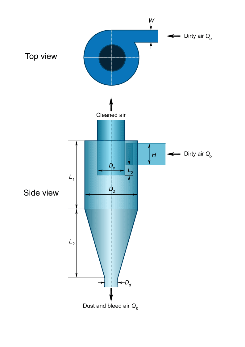
Reverse-flow cyclone of standard Lapple proportions, for gas–solid separation. Every dimension is a fixed multiple of the body diameter Dc, which makes the Lapple model the classical basis for the preliminary design of dust cyclones.
Lapple cyclone
Calculation methods
Sizing for a target cut size: body diameter and number of cyclones in parallel required to reach a given cut size within the maximum inlet velocity and pressure drop; also the pressure drop, blower power and principal dimensions.
Dimensions: cut size, inlet velocity, pressure drop, blower power and principal dimensions of a cyclone of known diameter.
Grade efficiency curve: collection efficiency as a function of particle size.
Dust split from the cyclone diameter and from the cut diameter: division of a particle size distribution into the collected (underflow) and escaping (overflow) streams, with the overall collection efficiency.
Model
For N identical cyclones in parallel, each receiving q=Q/N:
where Vi is the inlet velocity, Ne=6 the number of effective turns, NH=KHW/De2 the number of inlet velocity heads (K=16), ρp and ρ the particle and gas densities and μ the gas viscosity. Standard proportions: L1=L2=2Dc, H=De=Dc/2, W=Dd=Dc/4, L3=5Dc/8.
Design criteria
Inlet velocity between 15 and 25 m/s and pressure drop up to 2.5 kPa; both limits may be changed under Design coefficients. With NH=8, a pressure drop of 2.5 kPa in air corresponds to an inlet velocity of about 23 m/s, so the pressure limit generally governs the sizing.
Default properties: air at 20 °C and 1 atm, quartz particles (2650 kg/m³).
The model neglects mass loading and bypass and tends to overestimate the collection of the finest particles; it is intended for preliminary design.
References
LAPPLE, C. E. Processes use many collector types. Chemical Engineering, v. 58, n. 5, p. 144-151, 1951.
SHEPHERD, C. B.; LAPPLE, C. E. Flow pattern and pressure drop in cyclone dust collectors. Industrial & Engineering Chemistry, v. 31, n. 8, p. 972-984, 1939.
COOPER, C. D.; ALLEY, F. C. Air Pollution Control: A Design Approach. 4. ed. Long Grove: Waveland Press, 2011.
CIMBALA, J. M. Lesson 12B: Lapple Cyclone. A Practical Application of Inertial Separation.